HGT40 Thermal Relay 25A – A Curve
€20.09 Excl. VAT
Applicable Contactors HGC25-40
Product Attachment : PDF
Available on backorder
Description
– Thermal Overload Relay –
HGT40 THERMAL
When motor needs emergency stop during operation, it is possible to stop the
motor by cutting off its contact from the magnetic contact with test button.
• In order to test the operation of thermal overload relay
A (Auto) Mode: Auto reset
H (Manual) Mode: Manual reset contacts, immediate testing is possible by pulling
up test button which changes NO/NC contact.
– Protection Cover
•Operating side is covered with protection cover in order not to change the
settings and any operating arbitrarily.
•In order to change the settings, it can be changed by lifting up the protection cover.
– Test Button
•When motor needs emergency stop during operation, it is possible to stop the motor
by cutting off its contact from the magnetic contact with test button.
•In order to test the operation of thermal overload relay contacts, immediate testing
is possible by pulling up test button which changes NO/NC contact.
– Current Setting Knob
It is possible to set the rated current as 3 steps by using a +/- screwdriver.
– Reset Button
A (Auto) Mode: Auto reset
H (Manual) Mode: Manual reset
– Main Circuit Terminal
Screw type terminal is standard model, but for 40 – 100 AF, Lug type is available as an option.
– Safety Structures of TOR
•Attachment of protection cover
Prevents test function during operation and misoperation by user.
•Separation of reset button and test button
Prevents malfunction during operation.
– Phase Loss Protection: Differential Tripping Mechanism
•Differential tripping mechanism makes trip faster in the case of single phase loss
than all three phase overloaded condition. As shown in the figure, when R phase
in loss, the bimetal of R phase remains, so it fixes up the lower slide. At the same
time, the other bimetals of S and T phase are bent, then they move the upper
slide. It is also the same for S and T phase in loss.
– Technical Information –
Model (Basic) HGT40
Nominal Current 17 – 25 A
Max. Carrent 25 A
Characteristic Class A Curver
Auxilliary Contacts 1NO1NC
Reset Manual & Automatic
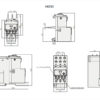
Dimensions (W x H x D mm) 45 × 95.5 × 69.4 mm
Weight 0.16 kg
– Selection Method –
-Short Starting Time Motors
•For the normal starting time motors within a few seconds relays can be selected by the table of page 56. The full load current
(FLC) of the motor must be in the setting range of the thermal overload relay. The starting time of high-inertia motor is an
important factor at the selection of thermal overload relays
•The tripping time of the motors, whose starting current is 6-7 times of the rated current, can be obtained from the HGT tripping
curves. This time should be longer than about 125 % of the motor starting time.
Long Starting Time Motors
•If the starting time of the motor is longer than the tripping time of HGT, the current transformer type is applicable.
•The current transformer type relays include the non-tripping features during the motor starting time. The rated current can be
decreased by looping primary cable several times on the transformer according to the following table.
– Order Code example –
1 Model: HGT
2 Applicable Contactor Rating: 18
3 Number of Terminal: k
4 Characteristics Class (Feature Curve): A
5 Setting Current: 18
6 Terminal Type: S
(see attached image)
Additional Information
| Weight | 0.2 kg |
|---|---|
| Dimensions | 5.5 × 12 × 8 cm |
| Hyundai | |
| Rated Current (A) | 25 |
| Maker | |
| Price € | |
| Frame | |
| Characteristics Class | |
| Number of Terminals |


